The X-Bone
Joe Touch and Steve Hotz
USC / Information Sciences Institute
(touch@isi.edu / hotz@isi.edu)
Nov. 8, 1998
The X-Bone is a system for the rapid, automated deployment and management of overlay networks. Overlay networks use encapsulation to enable virtual infrastructure, and they are being used more frequently to implement experimental networks and dedicated subnets over the Internet. Existing overlays, such as the M-Bone for multicast IP and 6-Bone for IPv6, require manual configuration and management, both to establish connectivity and to ensure efficient resource utilization. The X-Bone uses a graphical interface and multipoint control channel to manage overlay deployment at the IP layer, much like multimedia sessions are controlled via the session directory (sd) tool. The X-Bone enables rapidly deployable virtual infrastructure, that is critical to the development of both network and application services, and that is also useful for deploying isolated infrastructure for restricted purposes. This document describes the architecture of the X-Bone.
1: Introduction
Overlay networks are increasingly becoming necessary for general infrastructure support, used for developing experimental protocols and for emulating dedicated networks over shared infrastructure,
e.g
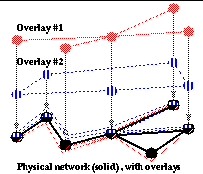
., to support emergency services and disaster relief (
Figure 1
). They allow a set of shared resources to emulate several separate sets of dedicated resources, and allow new protocols and services to be developed in a safe and contained environment. Overlays also may provide reserved service, effectively a `carpool lane' for each overlay's traffic. Additionally, overlay networks present a simplified network topology, so new protocols can be examined in controlled ways, without exposing the details of physical topology.
The general use of overlays is hindered by the tedious and complicated nature of configuration and management. Current overlay networks are configured manually, often requiring out-of-band (
i.e
., telephone or e-mail) communication with human network managers. These managers are expected to oversee deployment, and avoid inefficiencies such as redundant traversals of the same links, or oversubscription of resources. Furthermore, there is no current framework in which to detect or avoid inter-overlay resource contention.
The X-Bone is a system for the automated deployment of overlay networks. It enables users to deploy overlays without human network manager participation. It enables overlay networks to be deployed within seconds, rather than days. It manages inter-overlay resource contention by providing a uniform coordination point for overlays. This provides a framework for coordinating reservations, even between different mechanisms that manage a single class of resource. By making overlay establishment a fast, common function, the X-Bone enables new uses for overlays, such as for distributed applications without cumbersome application-level service location and routing support.
The X-Bone is also useful for testing new protocols. Even protocols designed for backward-compatibility or incremental deployment are best initially tested in a controlled environment. This includes end-to-end protocols, such as new TCP congestion control algorithms, so that testing can limit the effects of unforeseen bandwidth over utilization.
The X-Bone can be used to bootstrap and manage Active Networks (AN) infrastructure, deploying them as their own overlays. X-Bone also provides a platform to demonstrate the benefits of AN; although the X-Bone can be deployed prior to the availability of AN support, it can be implemented itself in AN technology.
The X-Bone system takes advantage of the opportunities provided by recent overlay network deployments and protocol developments. It emulates the development of the web, which combined simplified versions of established components, to implement a system that makes remote information access simple and ubiquitous. The X-Bone brings together a variety of independent mechanisms to provide accessible, ubiquitous overlay management. The X-Bone research helps pioneer new mechanisms for inter-overlay network management and coordination, by using multicast to simplify resource discovery and configuration management.
The X-Bone is composed of overlay managers, resource daemons, and a multicast control protocol. The overlay manager controls the deployment and configuration of an overlay, and is controlled by a user interface or programmable API. There are many such managers, running at user locations. The resource daemon runs at (or near) each resource, and provides access control, resource management, and security. It coordinates all X-Bone use of that resource. The multicast control protocol uses expanding-ring searches to locate available resources, and provides management control and feedback, as well as announcing channels for application use.
The remainder of this paper discusses overlay networks, and presents the X-Bone architecture, which is currently being implemented. It also discusses the issues in deploying the X-Bone, and some related research.
2: Introduction to overlays
Overlay networks are virtual topologies that use a combination of shared and dedicated resources, to provide a simple network view that conceals unnecessary details about the underlying topology. Overlay networks are composed of routing software installed at selected sites, connected by encapsulation tunnels
[15]
or direct links (
Figure 1
). Recent examples of overlays include the M-Bone for multicast IP
[9]
and the 6-Bone for IPv6
[1]
. A single physical network can support multiple overlays, which can share both link and node resources.
Today, deploying an overlay network is a manual process performed by human network managers. To deploy a single overlay network, the manager performs the following steps:
-
Obtain contact info. for managers at remote sites
-
Lay out the network topology
-
Assign the network addresses
-
Ensure your overlay doesn't interfere with others
-
Configure remote sites
-
In the case of a network problem, debug
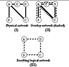
The X-Bone replaces this manual sequence with a graphical user interface tool and control and management algorithms to provide automated remote deployment. Consider the network in
Figure 2
(I), which consists of five nodes and five links.
Figure 2
(II) shows a ring overlay, consisting of three types of overlay links: <1> to partition the overlay from the existing network (AC, DC), <2> to bypass routers not participating in the overlay (AD
via
E, BC
via
A), and <3> to provide multiple virtual links over a single link (AB #1, AB #2). The overlay provides a virtual network of a ring of four routers (
Figure 2
, III). This basic example highlights some of the complexity of managing an overlay, where resources can be used for multiple paths (AB used twice), as transit (E), or as both (A as both participant and transit). Multiple overlays can map to a single physical network concurrently. In today's networks, nodes are typically part of a single overlay, although they may transit traffic for other overlays.
2.1: Current Practice
The simplicity of the above example belies the effort required to deploy such a virtual infrastructure in the Internet today. Consider how sites join the M-Bone.
First, IP addresses must be assigned to the nodes of the overlay. Then the local system administrator calls the network provider to determine the tunnel configuration, which both parties enter manually. In the case here, the entire overlay is composed of tunnels, even where overlay links map directly to physical links. This additional tunneling is required to separate the address space of the overlay from that of the underlying transit network.
Consider
Figure 2
again. The path between B-C is tunneled through A, and A-D is tunneled through E. The through-nodes of the tunnel, A and E, do not require specific configuration.; E is not even aware it is used as a tunnel. The tunnel encapsulation rules indicate how overlay addresses are to be encapsulated inside physical link addresses; default routing handles the further routing required.
Once tunnels are configured, default routes need to be added at the nodes. In this example, these routes are trivial,
i.e.,
at A, routes to the overlay addresses of B, C, and D are required. Although a simple topology is shown, it requires substantial effort, summarized as:
-
Assign addresses
-
Determine whether and where tunnels are required
-
Configure tunnels
-
Add routes
Each of these steps requires root privileges and remote login (telnet) for each host and router. Each step is entered manually; errors can cause the entire overlay and production networks to be disabled. Finally, it is difficult to configure multiple overlays when they use competing resources.
2.2: Desired Practice
The desired practice is fairly simple to specify. Consider the same network as
Figure 2
. Consider also that,
a priori
, sites A, B, C, and D are all running
xd
, the X-Bone interface tool, a version of an
sd
-like graphical interface and configuration management tool. In this case, the user selects the participating routers of the overlay, A, B, C, D, much as a teleconference organizer selects participants. In this case, the tool provides several simple default topologies, and the user selects `ring, in-order'. The rest, from addressing, to tunnel configuration, to routing, is handled automatically by
xd
.
Because
xd
manages the configuration, explicit remote logins or root privileges are minimized. Root-level configuration is done through the
xd
tool at each site, permitting access only to limited overlay functions. Of course, for each automated function, there should be a way for a privileged user to provide overrides. In this case, such overrides would be useful where manual addressing is preferred,
e.g
., to assign particular addresses. However, it is expected that as automated tools become more sophisticated, the requirement for manual override will become less frequent.
3: Architecture
The X-Bone architecture is based on a a two-level multicast control protocol, combined with algorithms to deploy and configure overlays. The architecture includes:
-
Overlay manager - configures and manages overlays
-
Resource daemons - manages resource use
-
Multicast control protocol - enables efficient resource discovery and management communication
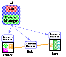
The following is a description of these components (
Figure 3
), and some issues in their implementation.
3.1: Overlay manager
The overlay manager (OM) runs inside
xd
, and it runs the algorithms that acquire resources, configure them, and manage them as a coherent overlay. Each overlay is ultimately managed by a single OM, which may delegate subtasks or sub-overlays to other OMs. The OM maintains the state of the overlay, including address usage, and resource allocation. This state allows coordination between overlays as well as coordination between separate reservation mechanisms. The OM is itself a component of
xd
, which also includes a graphical user interface and a port for program control via an API. The OM is also the primary active component, and initiates most of the configuration and management communication.
The user interface of
xd
is
loosely based (and perhaps implemented as a configuration of) the
sd
and
sdr
teleconference session control tools.
Sd
/
sdr
rely on multimedia tools (
vic
,
vat
,
nevot
) to monitor the status of a session,
e.g.
, to display the list of participants.
Xd
will provide a similar tool to view the network topology of each overlay system.
Xd
also supports user monitoring and manipulation of the overlay (
Figure 4
). Similar topology display tools,
e.g.,
GUILN
[10]
, are under development in the CAIRN project, but only for manual configuration, and for ATM networks.
The user interface includes controls to override automatic site selection and tunnel configuration parameters, and to deploy and delete an overlay. Access is provided
via
a graphical interface, as well as by a scripted control port, the latter supporting direct access by applications.
3.2: Resource daemon
Resource daemons (RDs) are persistent software processes running at or near resources, such as routers, links, and hosts. They keep state of the use of that resource, and coordinate how the resource is shared by multiple overlays. Initially, this state can be a simple counter, limiting the number of overlays in which a resource participates. Advanced RDs will interface to more specific control and reservation mechanisms, such as RSVP.
Resources that lack RDs do not participate in the X-Bone. RDs who use a binary counter can participate in only one overlay at a time; this ensures isolation of overlay resources in the simplest case. Advanced RDs can ensure isolation by managing the reservation of bandwidth, CPU, and memory within the resource.
As each resource in the network becomes a part of a shared set of overlapped overlays, more sophisticated resource sharing management is required, such as Internet Integrated Services for router sharing. Routers managed by the daemon will either be dedicated for experiments only, or have sufficient resource partitioning (process priorities, bandwidth reservation) to ensure isolation of production and experimental services.
Tunnels require the configuration of encapsulation and de-encapsulation mechanisms at each end of virtual link. Emerging tunnel management protocols for in-band control of the encapsulation parameters can be incorporated when available
[12]
.
Hosts require configuration of addresses for virtual interfaces as well as environments within the host used to select the overlay(s) to which an application communicates. Host virtual interface mechanisms, such as multiple IP addresses per interface (Solaris), or kernel patches for dummy internal interfaces (VIFs in SunOS) are required for multiple overlays given a single physical connection. Multiple physical interfaces suffice where policy routing on the host differentiates traffic destined for the separate overlays.
When global addresses are used, RDs are required to manage the address space. Initially, global addresses are used to keep overlay traffic partitioned, where each overlay has a distinct address space. This requires per-site RDs, to manage the available pool of addresses within a site. As the X-Bone is developed, more sophisticated tunneling and host demultiplexing capabilities allow overlays to have independent address spaces, in which addresses can be used without enforcing uniqueness. In this latter case, the address spaces can be managed within each overlay's OM, without the need for per-site RDs.
3.3: Multicast control protocol
The multicast control protocol uses a two-layer multicast IP system, similar to that used by
sd
/
sdr
. Multicast simplifies the resource discovery and route bootstrapping that is required for network management, by providing logical group names and self-configuring routing that is not otherwise ubiquitous in the Internet.
sd/sdr
use a common announcement channel (the first layer), in which an announcement indicates a separate set of channels for a session (the second layer), for each of audio, video, text, and shared whiteboard.
Xd
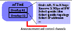
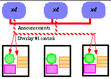
uses its first layer channel to exchange configuration and status information. Each overlay has its own, second-layer multicast control channel, which is announced on the main control channel. Each X-Bone tool listens to this channel and displays a listing for each advertisement received. Overlay announcements are handled much like teleconference sessions (in fact, they can be considered teleconferences among the automated resources) (
Figure 5
).
These channels can be used for resource discovery. Requests are sent on the main announcement channel, asking for resources. These requests are sent with limited TTLs (time-to-live), to restrict the extent of the announcement; if the request remains unsatisfied, a new message with a larger TTL is sent. Once the resources for an overlay are acquired, a control channel is created that reaches only that set of resources. The announcement of the created overlay may reach only that far, or may extend further, to indicate to other users (and applications) about the overlay.
4: Sharing issues
X-Bone resources are hosts, links, and routers. Hosts are data sources and sinks; links connect hosts to routers, and routers to each other. Routers are interconnections of links that do not source or sink data. Resources that are part of a single overlay are called dedicated; resources that are part of more than one overlay are shared.
Although addresses are not a resource
per se
of the X-Bone, address management affects all other resource sharing. The X-Bone operates at the IP layer, so resources must be labelled with IP addresses; this includes hosts, routers, and link tunnels. Addresses are either local to the overlay, or global to the Internet.
Global addresses allow simpler configuration of the X-Bone resources. Existing internet name service (DNS), and application interfaces suffice. However, this requires the X-Bone allocate and manage all overlay addresses globally, to ensure exclusive use; this is a non-trivial problem.
Local addresses allow richer overlays. A local address is interpreted within its own overlay, allowing address experiments to be replicated within an overlay, and allowing overlay users full freedom to manage their address space independently. This requires additional mechanisms in hosts and routers, to allow an address to be interpreted within the context of a particular overlay.
The mechanisms and requirements of the X-Bone are a result of supporting shared resources; these mechanisms are also affected by whether overlay addresses are globally unique or local to a single overlay.
Table 1
presents a summary of these requirements; these are discussed in detail below.
-
TABLE 1.
X-Bone Shared Resource Requirements
|
Resource
|
Sharing requirements
|
|
Host
|
multiple IP addresses
application overlay selection
|
|
Link
|
tunnel support
|
|
Router
|
tunnel support
partitioned route table
multiple forwarding engines
|
4.1: Host Sharing
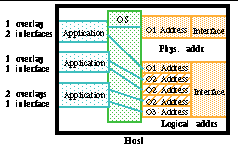
A host is a network endpoint for application access to overlays, and is defined by its interfaces. Different applications on one host might each access different overlays, or a single application may access multiple overlays (
Figure 6
). Hosts on multiple overlays require multiple network addresses, which requires either multiple interfaces or multiple addresses for one interface.
Hosts with multiple addresses are called `multihomed'
[3]
. Multihoming complicates packet addressing; packets sent out of the host must be stamped with a source address, and there is no convention for allowing applications to select that address. Common Internet practice is to give each interface one preferred IP address; for hosts participating in multiple overlays, this is not feasible. In addition, it is possible that different overlay addresses have the same IP address, where additional link labelling is used to demultiplex the packets.
e.g.
, for tunneling.
When addresses are local, or where the application needs to transparently participate in an overlay, the host application needs to determine these addresses. This is conventionally done in the DNS, but here the DNS needs to respond with overlay-specific IP addresses. In the X-Bone, application calls to
gethostbyname
(host1) can also be trapped in the OS or library, and replaced with
gethostbynameenv
(host1, environment(overlay_name)). The overlay can alternately be determined by state outside the application, such as user input or per-window environment variables
[5]
.
The endpoint hosts require some combination of virtual addressing, multiple physical addresses, and policy routing
to allow them to participate in multiple overlays. The various combinations ensure that the host has sufficient information to demultiplex packets internally (e.g., policy-based routing) or that the first-hop router from that host has already demultiplexed the packets to separate destination addresses. The difference is whether the labelling occurs at the IP layer (for virtual and multiple physical addresses) or at an interior label (for policy-based demultiplexing or routing).
4.2: Link Sharing
Shared links require virtual endpoint addresses at the routers or hosts, similar to the virtual IP addressing of shared host interfaces. Shared links can additionally require encapsulation or decapsulation mechanisms at these endpoints. Dedicated links can be assigned endpoint IP numbers for their particular overlay, while multiple physical interfaces on a host each have their own address. The support for multiple IP numbers on a link is provided at the host or router interface by assigning multiple IP addresses to the interface.
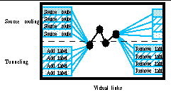
Virtual links can use either source routing or tunneling (
Figure 7
). Source routing requires the addition of path information at the source only, either inside individual packets or as persistent state at intermediate routers in the path, but the length of the source route (physical hops per virtual path) is often limited. Tunneling relies on existing network state, and hides the entire packet contents in a new header with a label; tunneling has no limit to the length of the virtual path, but requires de-encapsulation at the destination end.
4.3: Router Sharing
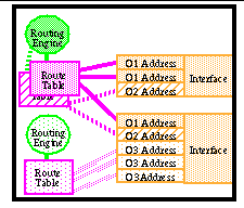
Routers are composed of link interfaces (line cards), routing tables, forwarding algorithms, and routing algorithms (
Figure 8
). The link interfaces are the router equivalent of host network interfaces. Routing tables store information that is used to forward packets. The packet forwarding algorithm determines how packet information is used to select a route from the routing table, to select an outgoing link and modify packet information. The routing algorithm manages the routing tables, how tables entries are communicated among routers, and how shared information is used to recompute the route table. Each of these resources may be shared.
Routers are already shared in the Internet. Sharing routers among multiple overlays is trivial, if the overlay links and their addresses do not overlap. Their routing tables do not require further sharing support, because the overlays naturally partition the routing table.
If links are shared or if overlay addresses are local, the router requires virtual link labelling and demultiplexing,
i.e.
, tunnel support. The routing table must also be partitioned, and selected based on a packet's overlay indicator (incoming virtual link label if locally addressed, or its IP address if globally addressed). The overlay can also determine the forwarding algorithm, such as shortest-path or policy- or QoS-sensitive.
4.4: Inter-overlay and intra-overlay sharing
A key feature of the X-Bone is its ability to coordinate between concurrent overlays where they share resources. The X-Bone helps this coordination, by supporting monitoring software to validate reservations or maintain counts of how many overlays share a device. Such counts can be signalled to a human network manager, or used to provide coarse sharing limits. Bounds checking algorithms will be employed to monitor and flag inter-overlay contention, and inhibit overlay deployment where resolution is not otherwise possible.
This broad coordination of overlays requires a scalable contention detection and resolution mechanism. Initially, this can be provided by permitting an overlay only where contention avoidance can be detected, and defaulting to a conservative `prohibit' response otherwise. Probabilistic guarantees can also be employed, where over-provisioning (or under-allocation) can be used to infer resource availability.
4.5: Security management
The X-Bone is an inherent security challenge, because it provides remote access to routing configuration. The X-Bone tool uses only `willing' resources to participate in various overlays. The X-Bone is intended to be deployed only on shared and shareable resources; resources for which security has not or cannot be sufficiently ensured are not participants in the overlay, other than as a transit for packets, a service which they already provide (or otherwise constrain). The extent of the sharing is controlled by the API and configuration by the owner of each resource.
In its initial deployment, the tool will be additionally constrained,
e.g.
, to use only `private' IP addresses
[13]
, and to limit its access to router resources. The early systems will be deployed with a single, global encryption and authentication key, to avoid spoofing and intrusion.
Initially, messages over both the single announcement channel and the per-overlay channels are authenticated
via
a single, global password. Per-group passwords, encryption, and automated key management will be incrementally incorporated into the X-Bone tool implementation. The emerging standard IP security protocols will be used for authentication and encryption services.
5: Optimization to the underlying network
Human network managers provide two important functions in the current scheme for overlay deployment, both in providing overlay configuration, as well as in analyzing overlays to avoid interference with the underlying topology. We have described how the X-Bone replaces them in the former case; in the latter case, the X-Bone can provide a level of optimization that manual management cannot achieve.
Simple optimizations include avoiding redundant link traversals within a single overlay, and ensure hopcount-limited deployment. More sophisticated optimizations apply bin-packing heuristics to multiple overlay sharing, to maximize the number of overlays supported on each shared resource. Similar optimizations have been developed for telephony at the call level; the X-Bone imports these techniques, treating overlays as multiparty `calls.'
Other optimizations are used to ensure user constraints, such as latency limits, jitter aggregation limits, and other performance constraints. Although such optimizations are seemingly unlimited, the deployment of simple optimizations, together with community feedback, can help develop tools to enhance network utilization, maximize sharing, and minimize contention.
6: Prior and Related Work
The X-Bone generalizes and automates the deployment and management of overlay networks. There have been many overlay network instances, which provide the motivation for providing a general control system. The X-Bone system is a simpler, less generic IP-only version of other multi-layer or multi-capability network deployment tools, such as Supranets and MorphNet. It takes advantage of the recent developments in emerging support for programmable routers (Active Networks), remote tunnel management and security architecture. The X-Bone can capitalize on, but does not rely on any of these developments to deploy immediately. The X-Bone also serves as a framework to coordinate and manage other new mechanisms (
e.g
. multiprotocol label switching
[4]
) within overlay networks.
6.1: Virtual networks
The X-Bone is a direct descendant of the M-Bone
[9]
and its recent clone, the 6-Bone
[1]
. The M-Bone supports multicast IP by using routers that implement a superset of the IP routing algorithms used elsewhere in the Internet, and encapsulating otherwise incompatible multicast IP packet inside conventional IPv4 packets. An M-Bone router, although linked to other M-Bone routers
via
IP tunnels, is also a proper member of the Internet itself as well. Similarly, the 6-Bone supports IPv6 by encapsulating IPv6 packets in IPv4, and providing IPv6 routing capability only at selected intermediate routers.
One of the earliest examples of overlay networking was the use of IP to support OSI/CNLP links
[11]
. In this system, the early Internet was used as a virtual network over which OSI network-level protocols were tested.
MorphNet is similar to the X-Bone, although encompassing many levels of virtualization
[2]
. The X-Bone can be considered an IP version of MorphNet, but MorphNet focuses on the incorporation of heterogeneous systems of overlays at these different levels.
The Metanet, proposed by Wroclawski at MIT, addresses the membership issues of the X-Bone
[20]
. It defines regions as a level of aggregation of network resources, and focuses on a higher-level of basic communication, perhaps as a redesign of IP.
Turner and Mankin also propose virtual networks composed at the ATM level
[18]
for the CAIRN network, due to existing bandwidth allocation and enforcement at ATM switches. ISI's GUILN is an ATM graphical user interface for managing logical ATM networks
[10]
. It provides manual configuration of a virtual net from a single remote site.
The Supranet is the project most similar to the X-Bone; it is being developed in the CRATOS group at the Catholic University of Piacenza, Italy
[6]
. It focuses on optimizing the topology and resources of the virtual network to the physical network, and operates predominantly at the IP layer. In many ways, the X-Bone is the HTML to Supranet's SGML; a simple subset designed to be rapidly deployed and evolved.
Any application-level routing is,
per se
, an overlay on the conventional network-layer routing services. One recent example of application routing is distributed web cache proxy systems, such as ISI's LSAM
[17]
and UCL's CacheMesh
[19]
. In such systems, an client application contacts a primary proxy, which directs the request within a set of second-level proxies. This is equivalent to application-level routing, and acts as an overlay on the network-layer routing provided by TCP/IP and IP addresses of the proxies.
The NetScript project addresses the deployment of virtual networks in particular, as NetScript Virtual Networks (NVNs)
[21]
. NVN focuses on a common router programming language, and describes the general notion of coordinated deployment and management. The X-Bone is envisioned as the upper-level interface to a system that includes a variety of mechanisms, including NetScript and NVN.
6.2: Other virtual networks
Virtual Private Networks (VPNs) refer to the efforts to provide secure virtual private networks over public IP network infrastructure by combining tunneling mechanisms and mechanisms for IP security
[8]
. X-Bone will use the IP security framework in a similar manner to provide for secure overlay networks. X-Bone faces similar challenges with the use of private address spaces within the public infrastructure. Whereas VPNs suggest use of network address translators to deal with legacy address assignment, X-Bone's inherent ability to rapidly choose and deploy virtual addresses affords an alternative solution to this problem.
Multiprotocol Label Switching is an emerging IETF standard for simplified forwarding of layer 2 based on label swapping
[4]
. These mechanisms provide for more efficient tunneling of link-layer PDUs. The X-Bone will be able to manage and configure overlays using the MPLS interfaces. MPLS allows the X-Bone to achieve tunneling with the performance of switching, with the control of source routing.
7: Summary
The X-Bone provides a configurable virtual networking infrastructure, critical to the development of both network and application services, and is equally useful for deploying isolated infrastructure for restricted purposes,
e.g
., an emergency communications network for disaster management. It provides isolation between overlay networks. It also provides a partitioning of resources that allows experimental overlay networks to avoid interference with production services, and allows overlay testbeds to guarantee their own service for dedicated experiments. In this way, overlays can provide per-testbed virtual networks using both public production services and dedicated resources, such as the bandwidth resources of the vBNS backbone.
Example uses of X-Bone include: a NG-Bone can be deployed to test next-generation protocol capabilities without disrupting existing protocols; an emergency-services overlay backbone can be deployed quickly, in which capacity is reserved on the tunnel links to ensure traffic priority; a military brigade can deploy a backbone for temporary private network service using existing encrypted link technology.
The X-Bone's coordinated management supports both long-lived and short-lived large scale overlay networks with little manual intervention. As compared with manually-configured counterparts, the X-bone is easier to use, is being deployed sooner, incrementally incorporates new networking technologies, and provides both fence-in (contain the overlay from affecting others) and fence-out (prevent others from encroaching on the overlay) isolation.
The X-Bone uses an interface and resource discovery protocol adapted from the
sd
and
sdr
M-Bone tools
[14]
.
Sd
and
sdr
are session directory tools that advertise multiple M-Bone multicast sessions on a single, global multicast channel. A similar X-Bone directory tool,
xd
, provides an equivalent interface to multiple X-Bone overlay networks.
The X-Bone consists of components which challenge fundamental design principles of both integrated and host-based routers, as well as end-system configuration. The X-Bone is based on gradual deployment, integrating advanced capabilities incrementally, both by internal development and synergy with emerging research efforts. The X-Bone will utilize advanced network services as they become available, including Active Networks, group security, in-band tunnel and encapsulation management, and resource reservation mechanisms. For components that are difficult to implement completely, there are trade-offs that can achieve reasonable initial functionality in the very near term. The full capabilities of the X-Bone are not dependent on any particular implementation or research result, however.
The X-Bone also provides a mechanism by which Active Networking components can be deployed and managed. This allows heterogeneous AN nodes to be deployed on separate overlays, or as part of an integrated AN overlay. This ability to rapidly deploy and associate AN nodes serves a complimentary function to AN's ability for rapidly introducing new network functions. X-Bone provides a unique use for ANs, notably to build separate packet processing engines and routing tables in routers, which will enable contained overlapping overlays without requiring address independence. As the conventional use of AN seems to be the introduction of an independent new service into a routing node, the X-Bone provides a novel use for AN capability.
The X-Bone architecture, presented here, was completed in Spring 1998, and a prototype is expected in the Fall 1998. The authors would like to thank Bill Manning and Ted Faber of ISI's Computer Networks Division, Rich Carlson of the Argonne National Lab, Bob Aiken of the Dept. of Energy, and the participants of the Cluster Interconnects Working Group for their feedback on earlier versions of this document.
8: References
-
[1]
6-Bone web pages -
-
[2]
Aiken, R., Carlson, R., Foster, I., Kuhfuss, T., Stevens, R., and Winkler, L
.
, "Architecture of the Multi-Modal Organizational Research and Production Heterogeneous Network (MORPHnet)" Tech. Report ANL-97/1, Argonne National Lab, IL., Jan. 1997.
-
[3]
Braden, R., ed. "Requirements for Internet Hosts -- Application and Support," Internet RFC 1123, IETF, Oct. 1989.
-
[4]
Callon, R.,
et al
., "A Framework for Multiprotocol Label Switching," Ascend Communications, (work in progress - Internet Draft), 11/26/1997.
-
[5]
Carlson, R., personal communication, Sept. 1997.
-
[6]
Delgrossi, L., Ferrari, D., "A Virtual Network Service for Integrated-Services Internetworks," 7th International Workshop on Network and Operating System Support for Digital Audio and Video, St. Louis (Missouri), May 1997.
-
[7]
Demizu, N., and Izumiyama, H., "Dynamic Tunnel Configuration Protocol," SonyCSL, Inc., (work in progress - Internet Draft), 12/04/1997.
-
[8]
Doraswamy, N., "Implementation of Virtual Private Network (VPNs) with IP Security," FTP Software, (work in progress - Internet Draft), 03/14/1997.
-
[9]
Eriksson, H., "MBone: The Multicast Backbone,"
Communications of the ACM
, Aug. 1994, Vol.37, pp.54-60.
-
[10]
GUILN web pages -
http://www.cairn.net/guiln.html
-
[11]
Hagens, R., Hall, N., and Rose, M., "Use of the Internet as a Subnetwork for Experimentation with the OSI Network Layer," Network Working Group RFC-1070, Univ. Wisconsin - Madison and the Wollongong Group, Feb. 1989.
-
[12]
Hamzeh, K., "Ascend Tunnel Management Protocol - ATMP," Internet RFC 2107, Ascend Communications, Feb. 1997.
-
[13]
Rekhter, Y.,
et al
., "Address Allocation for Private Internets," Network Working Group RFC-1918, Cisco Systems
et al
., Feb. 1996.
-
[14]
sd
tool web pages -
ftp://ftp.cs.lbl.gov/conferencing/sd/
-
[15]
Simpson, W., "IP in IP Tunneling," Internet RFC 1853, Daydreamer, Oct. 1995.
-
[16]
Tennenhouse, D.L., Smith, J.M., Sincoskie, W.D., Wetherall, D.J., Minden, G.J., "A survey of active network research,"
IEEE Communications Magazine
, Jan. 1997, pp. 80-86.
-
[17]
Touch, J., and Hughes, A., "The LSAM Proxy Cache - a Multicast Distributed Virtual Cache," 3rd International WWW Caching Workshop, Manchester, England, June, 1998. Also in Computer Networks and ISDN Systems (to appear).
-
[18]
Turner, J., Boroumand, J., Mankin, A., "ATM: The Design Tool for Networking and Distributed Systems Research," Next-Generation Internet (NGI) Workshop white paper, April 1997.
-
[19]
Wang, Z., Crowcroft, J., "Cachemesh: A Distributed Cache System For World Wide Web," NLANR Web Cache Wk., Boulder, Jun. 1997.
-
[20]
Wroclawski, J., "The Metanet," NGI Workshop white paper, April 1997.
-
[21]
Yemini, Y., da Silva, S., "Towards Programmable Networks," Columbia Univ. Tech. Report (unpublished), 1996.
-
[22]
Zhang, L., Deering, S., Estrin, D., Shenker, S., and Zappala, D., "RSVP: A New Resource ReSerVation Protocol,"
IEEE Network
, Sept. 1993.
